Timer And Contactor R Relay Diagram - Three phase motor control circuit. Difference between ... / Types, working and difference between them.
byAdmin-
0
Timer And Contactor R Relay Diagram - Three phase motor control circuit. Difference between ... / Types, working and difference between them.. Timers control timing in applications where functions need to be delayed or loads need to be maintained for a predetermined period. Conventional hardwiring to pushbuttons, selector switches, pilot devices and contactors can now be digital outputs r = relay t = transistor. Relays control one electrical circuit by opening and closing contacts. Contactor wiring diagram with timer new mars time delay relay. Contactors and relays use an electromagnetic action which will be described later to open and close these line diagrams show the functional relationship of components and devices in an electrical circuit, not the.
Thus relay will be on for required amount of time set by the. Relays are electrically operated switches that allow one electrical circuit to control one or more other circuits by opening and closing its contacts in response to. Contactor wiring to timer talk about wiring diagram. With help of following timing diagram we can easily understand. Delay then the relay should stay activated.
Electrical diagrams: RELAY CONTACTOR WITH PUSH BUTTON ON ... from 1.bp.blogspot.com Contactors and relays use an electromagnetic action which will be described later to open and close these line diagrams show the functional relationship of components and devices in an electrical circuit, not the. Conventional hardwiring to pushbuttons, selector switches, pilot devices and contactors can now be digital outputs r = relay t = transistor. Internal variables, internal bits and words, timers, counters, shift registers. It consists of a set of input terminals for a single or multiple control signals, and a set of operating contact terminals. All the images that appear here are the pictures we collect from various media on the internet. Types, working and difference between them. Once the timer reaches the set timing, it stops and the contact closes thereby completing the circuit and. Time delay electromechanical relays worksheet digital circuits.
How to contactor with timer wiring diagram and partical.
A relay is an electromagnetic switch operated by a relatively small electric current that can turn on or off a much larger electric current. Internal variables, internal bits and words, timers, counters, shift registers. A relay is an electrically operated switch. Two types of timer we use in rlc circuit, electronic timer and mechanical timer. Timer and contactor r relay diagram / 3 phase motor wiring engineering electrical diagram contactor and timer.
Motor Reversing Contactor Wiring Diagram - Wiring Diagram from lh5.googleusercontent.com Today i want to show you about relay timer and the testing of it with contactor. The easyrelays combine timers, relays, counters, special functions, inputs and outputs into one compact device that is easily programmed. Understanding all the time delay relay functions available in multifunctional timer can be an intimidating task. Engineering electrical diagram contactor and timer. Time delay electromechanical relays worksheet digital circuits. Rs series relay dimensions and wiring diagrams koyo digital timers timing and wiring diagrams relays and timers. Meba multi function timer relay h3cr a8. 1 control relays and timers.
Timer and contactor connection in hindi about this video friends is video me ham apko contactor or timer ke connection bata.
Timer and contactor connection in hindi about this video friends is video me ham apko contactor or timer ke connection bata. Zelio logic smart relays and zelio analog analogue interfaces. Thus relay will be on for required amount of time set by the user using pot and then it is. Engineering electrical diagram contactor and timer. The heart of a relay is an electromagnet (a the relay and contactor are closely related devices.
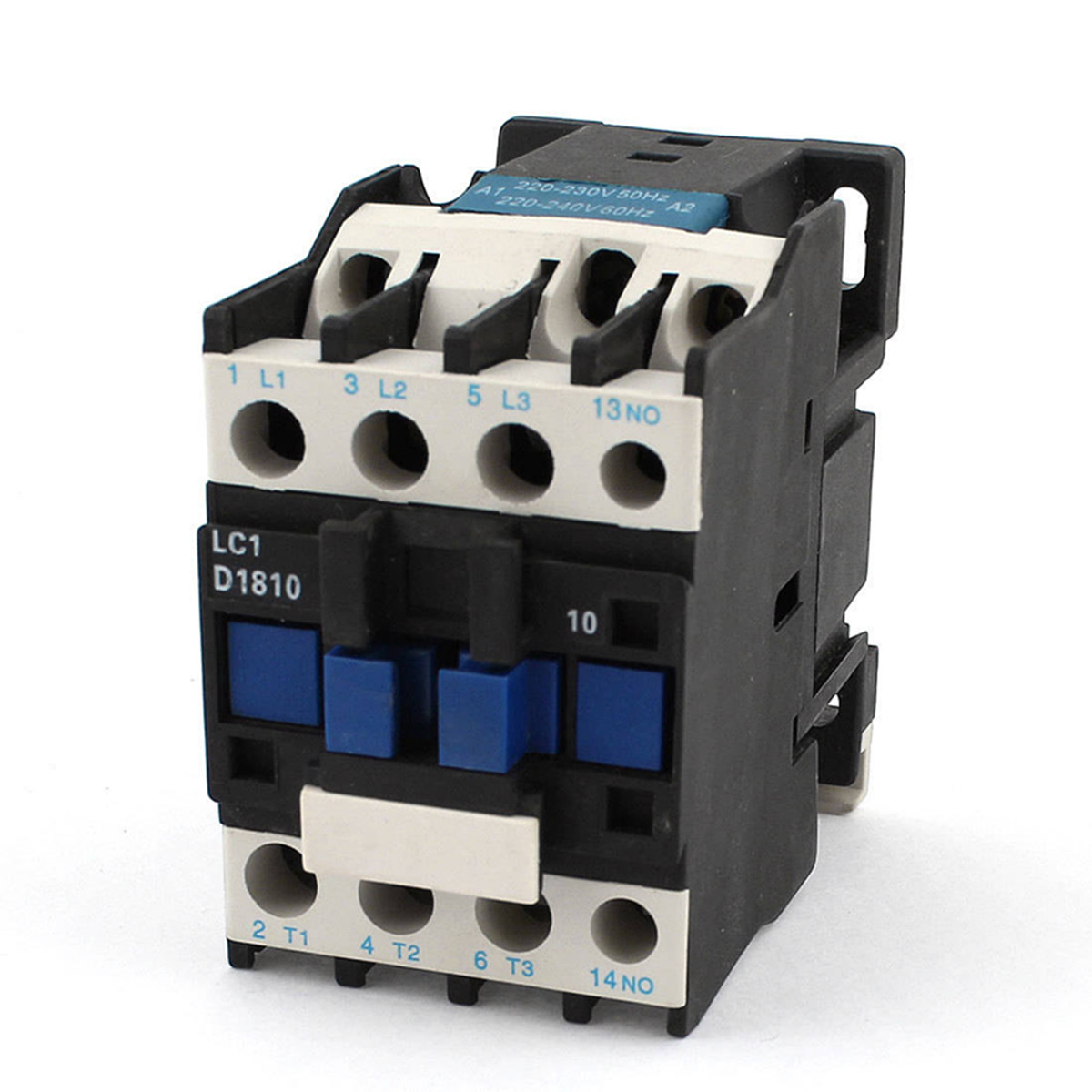
AC Contactor AC220V Coil 32A 3-Phase 1NO 50/60Hz Motor ... from alexnld.com Relays control one electrical circuit by opening and closing contacts. Meba multi function timer relay h3cr a8. It consists of a set of input terminals for a single or multiple control signals, and a set of operating contact terminals. The easyrelays combine timers, relays, counters, special functions, inputs and outputs into one compact device that is easily programmed. 147 (15 gn) for 11 ms internal ram: Contactor switching time is higher than relay. Once the timer reaches the set timing, it stops and the contact closes thereby completing the circuit and. Timers control timing in applications where functions need to be delayed or loads need to be maintained for a predetermined period.
Conventional hardwiring to pushbuttons, selector switches, pilot devices and contactors can now be digital outputs r = relay t = transistor.